GD&T analysis
Effective communication and consistent measurement across all engineering disciplines and processes are fundamental to the design and manufacturing of the highest quality products. GD&T is crucial to achieving these goals.
As a tool, GD&T has been used in the automotive, aerospace, electronics, commercial design, and other manufacturing industries for the last few decades to improve product quality. Its use has grown in tandem with the industries’ move from mechanical drawings to digital design.
GD&T ensures that parts fit and function properly. It is a symbolic language to perfectly capture the design intent.

Manage part complexity with Metrolog X4 GD&T processing engine
How GD&T can improve your quality control
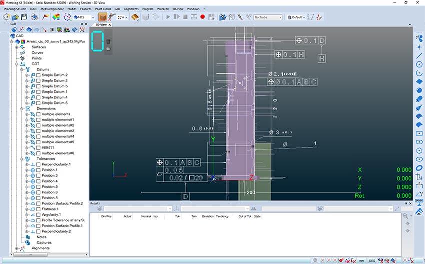
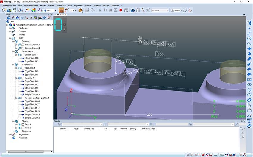
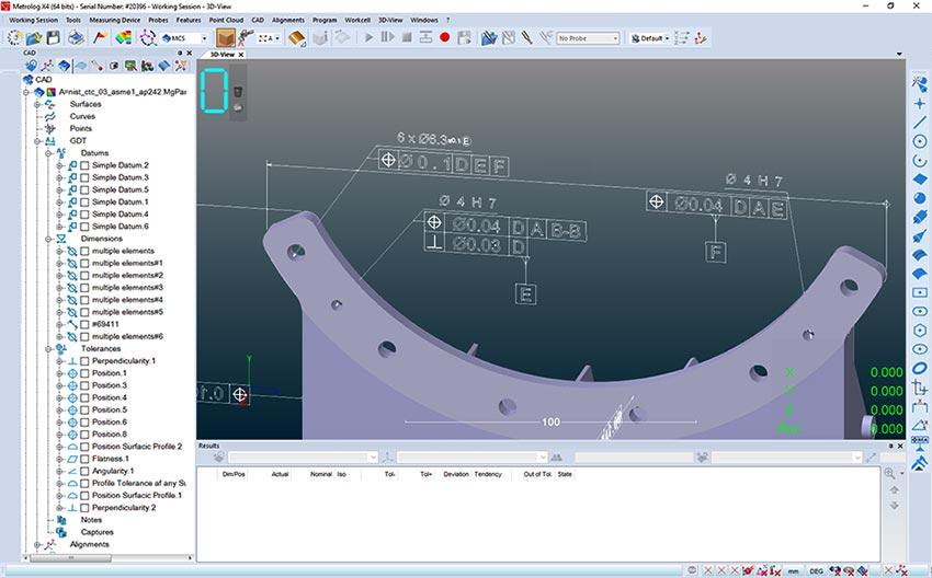
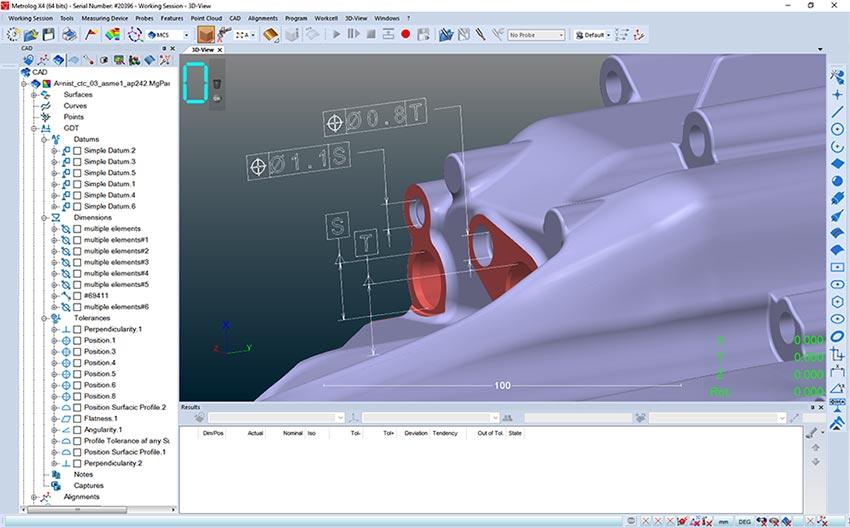
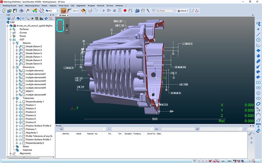
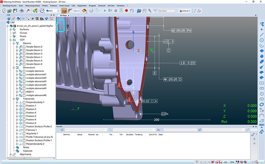
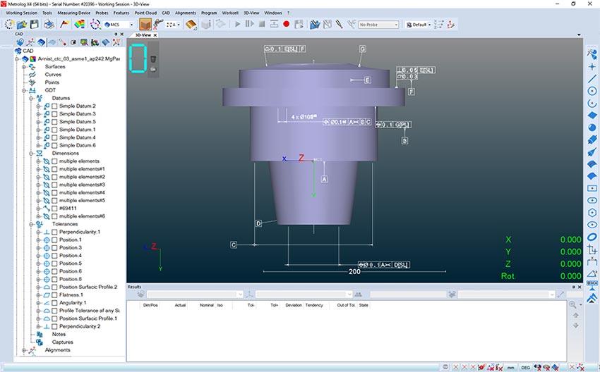
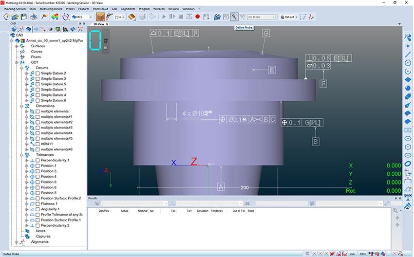
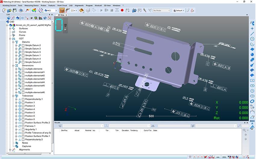
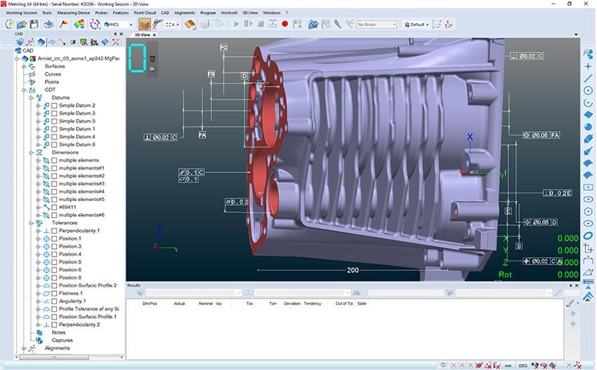
More GD&T are currently embedded into CAD files with Product Manufacturing Information (PMI). Not only do quality engineers have to access these data sets, but they also need to decode the engineering intent. Additionally, international GD&T standards keep evolving adding rooms for interpretation and costly errors.
Our Metrolog X4 software provides a comprehensive set of GD&T tools to intelligently guide the user through an effective workflow with precise understanding of the state of the part, possible sources of stack-up errors in assemblies by simultaneously working with many results, and obtaining sharp and usable information from the analysis.
The hands-on approach of advanced algorithms and calculation methods makes GD&T easy to master for busy engineers who have many other responsibilities or users without extensive GD&T proficiency.
Ensure inspection consistency
Metrolog currently support the following CAD files embedded with PMI:




Metrolog has a GD&T processing engine for handling the most complex cases in record time.
NIST-PTB certified results give you the confidence to inspect accurately and quickly. Metrolog features allow you to shape reliable and consistent inspections with total traceability throughout the entire process.
The Metrolog engine allows deleting intermediate steps; no need any more for operator to know which algorithm or constraints need to be apply to such feature or datum. Metrolog will handle it automatically in respect to standard requirements. When evaluating a GD&T in Metrolog, Datum reference frame (DRF) are automatically created; degrees of freedom are automatically selected depending on DRF, avoiding possible user interpretation errors. Optimization is also carried depending on tolerances zone shape.

Ensure all aspects of manufacturing, from engineering to final inspection, are performing to their full potential in producing good parts quickly and inexpensively.
Reduce scrap and rework
Metrolog provides stunning GD&T report capabilities:
- Table results with numerical values, go no go states…
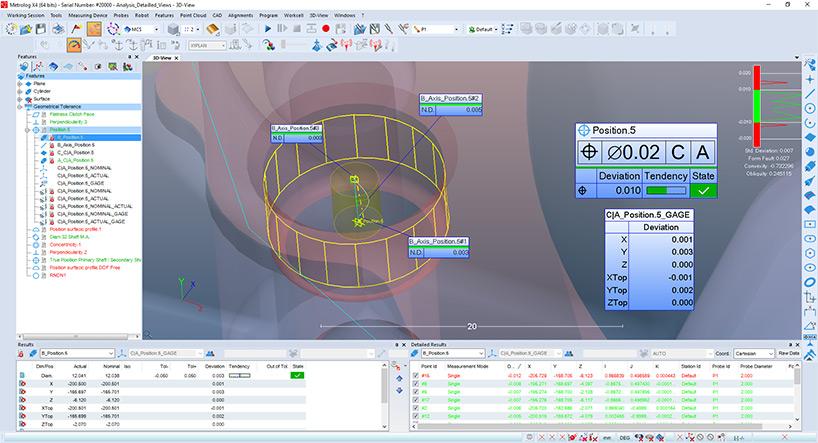
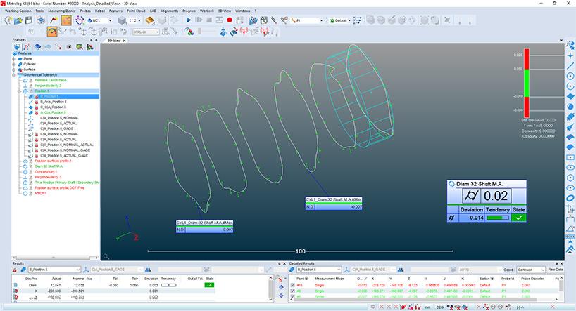
- Graphical views with labels presenting results of GD&T calculation next to the GDT cartridge…
- In addition, provide many dedicated detailed views to illustrate the GD&T results. Those details view are readable and very useful for machining operator to show them where, why and how to setup/adjust correction to their production machine.
Metrolog GD&T engine can handle both ASME and ISO standards.
