Within the large machine manufacturing industry, operators are faced with a number of challenges when it comes to measuring a large part. These challenges include:
- Using special equipment to move large parts, as these are cumbersome and not easy to move.
- Some parts, in industries such as aviation, are very expensive and need to be measured during the production process to ensure they conform to measurements and standards at all times. Waiting until the end of the process and finding an error can result in loss of production days.
- CMM machines are fixed and cannot be taken to the part.
- There will be points that need to be measured but are hard to access.
- During the maintenance process some objects, such as ships, are simply impossible to move but still need to be measured.
Measure large objects by moving the portable 3D device to the object. Portable 3D devices can provide accurate measurements when measuring large parts.
1/ Streamlined Solutions for Efficient Large-Part Measurement
The first solution in measuring large parts is simply to move the portable device (arm, tracker, laser or POD) to the part and take the measurement.
Obliterating the misconception, the part needs to be taken to the laboratory or multiple machines need to be used to take the measurement.
A portable arm can be fixed to a tripod using a magnetic plate and will measure a part that is 1m x 0.5m. This usually fulfils around 80% of measurement requirements.
2/ Mastering Alignment: Key to Precision in Large-Part Measurement
The next step is to create an alignment for accurate measurements. Although this sounds straightforward it too can come with its challenges.
Start with the drawings to understand what the measurements and tolerances should be. Ensure the part being measured is fixed. The key part is to find the reference point, so all the measurements are taken from the correct starting point. The software should show which features need to be measured and provide step-by-step guidance to locate the reference point.
The measuring device needs to be placed in the best possible position to take the measurement. A good software package allows operators to tell it what needs to be measured and the software program automatically calculates the best positions in which the measuring device should be placed at. This usually involves moving the portable measuring device around the large object, e.g., a boat. Taking the measurements from these best positions saves times as it minimize the number of positions to move device.
Should a software package fall short and not show which best positions the portable measuring device should be placed at, multiple measurements will have to be taken which is time-consuming.
Another possible drawback is losing accuracy when the device is used and not placed in the best position to take the measurement
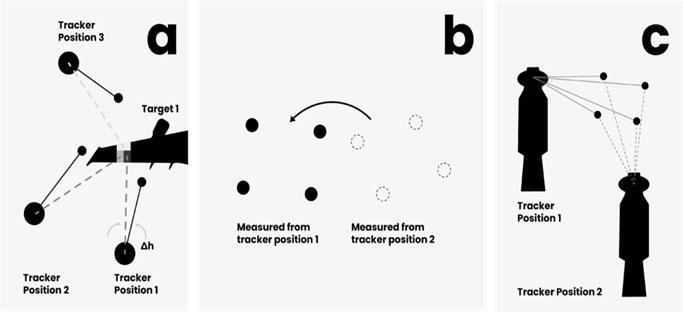
Once the alignment has been created, a correlation needs to be established between the first and second stations to make sure the measurement is correct.
Each station comprises of at least three reference points and measurements are taken using the beams on a tracker at each of these points. The process is repeated at the second station. The data from these two stations is used to create a correlation by the software. This is known as creating a bundle to find the alignment.

It’s somewhat easier to find some reference points on geometric shapes and can be more challenging on freeform parts.
When taking measurements, the tolerance levels also need to be adhered to, as set out by ISO or ASME. It is important to note that these standards are revised regularly so organisations should ensure that they receive patch updates to their software to stay up to date.
3/ AT-A-GLANCE: Steps To Follow
- Refer to drawings to obtain the measurements
- Drawings show the reference point to create the alignment and which features need to be measured
- Input what features need to be measured into the software
- Software shows the operator the best position to place the measuring device
- Place measuring device in the said positions to create the alignment
- Carry out the measurements on reference points, moving the measuring device, as this creates the correlation bundle – i.e. the correlation between stations one and two – very easy and quick. The software algorithm is powerful and accuracy will be maintained
- Operators can preview the results and determine from the colour coded image whether the results are accurate (e.g. green is accurate, red is inaccurate)
4/ Automated Reporting: Identifying and Solving Production Errors Effortlessly
A report should automatically be generated by the software application and show at a glance where the errors are instead of simply rejecting the part. This will help pinpoint where the error has occurred in the production process and will therefore be easier to locate and rectify.
A graphic colour coded map can easily diagnose precisely where the error is and how they can be corrected. It will make recommendations on changes that need to be made to the production process to get the required part.
5/ What is the main benefit?
A turnkey solution will save time and money as it’s easier to program and users can be trained quicker.
