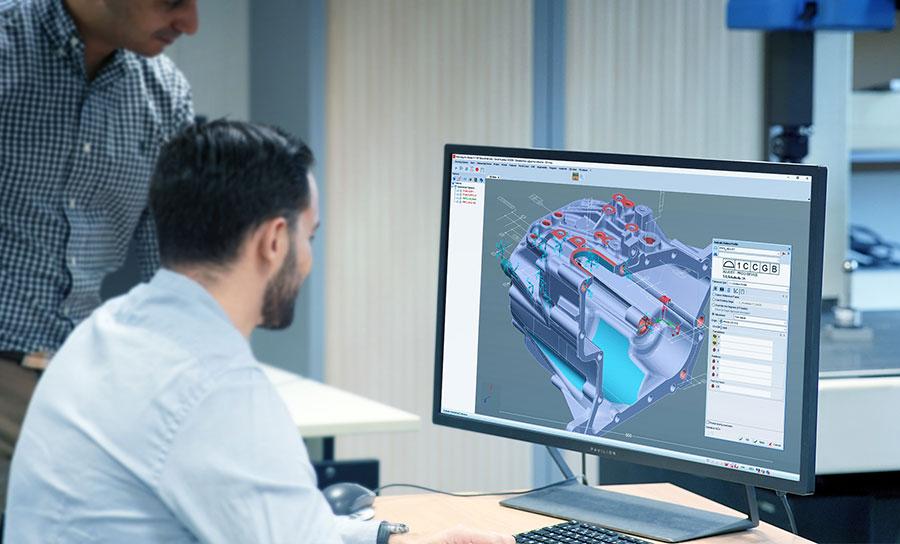
Geometric Dimensioning and Tolerancing (GD&T) is a system that is used to define and communicate engineering tolerances particularly in the automotive, aerospace, electronics and commercial design industries for the past few decades.
The main purpose of deploying GD&T is to ensure that parts fit and function properly by telling manufacturing staff and machines the degree of accuracy and precision needed on each controlled feature of the part.
It does this by using a symbolic language on engineering drawings and computer-generated 3D solid models that clearly explain the theoretically perfect – or nominal – geometry of parts and assemblies as well as the allowable variation for the form, the possible sizes of the features and the spaces between the features.
Which measurement standards are followed in GD&T?
There are three specific measurement standards which are adhered to when GD&T is deployed:
ASME Y14.5-2018 – Dimensioning and Tolerancing:
This standard is considered to be the authoritative guideline for the design language of GD&T.
ISO TC/10 – Technical Product Documentation
The overall aim of the ISO TC/10 standard is to help those implementing it to experience key benefits.
ISO TC/213 – Dimensional and geometrical product specifications and verification
This set of standards particularly focuses on tolerancing, specification and verification of mechanical components.
For more technical details on those standards, you can move forward to the end of this article in order to know a little bit more.
How to apply GD&T for improved 3D quality control
Quality engineers have to keep these important aforementioned standards in mind that are continually evolving in tandem with industrial modernization, legislation and compliance requirements. They also have to access data sets and decode the engineering intent, keeping a continual eye on avoiding costly measurement errors.
This is why investing in a suitable 3D metrology software solution that provides a comprehensive set of GD&T tools helps to:
- Intelligently guide the user through an effective workflow with precise understanding of the state of the part
- Identify possible sources of stack-up errors in assemblies by simultaneously working with many results
- Obtain sharp and usable information from the measurement analysis
- Enable engineers to develop a hands-on approach to gain GD&T proficiency rather quickly because of advanced algorithms and calculation methods.
- Ensure inspection consistency with the relevant cad files being embedded within product manufacturing information (PMI) thereby increasing production rates.
When correctly and compliantly applied, GD&T ensures that all aspects of manufacturing – from engineering to final inspection – are performing to their full potential in producing good parts quickly and inexpensively.
What are the key benefits of exploiting GD&Ts in your metrology software?
Designing, manufacturing and controlling based on high technical standards through GD&T is key to ensure that your parts, subassemblies and systems globally runs and deliver results on the field as expected. But what can you expect when using your metrology software with all those GD&Ts?
First and the most important, being able to create programs that sticks exactly to what you need to control, nothing less, nothing more.
Then, in a software such as Metrolog X4, you will be able to generate programs very fast as this software will read, understand constraints and compute the most optimized paths and control steps for you to reach your results … in a few clicks!
In the end, after saving time programing and executing all your controls, you’ll be able to deliver optimized reports displaying results the way they need to be displayed: complying to the standard code you follow, with views and easy to read values.
Sticking to a standard like ISO or ASME can be painful and time consuming… unless you choose to work with a metrology software able to take on this daily challenge.
You probably have a skilled collaborator in your teams, and that’s great! But feel free to release the repetitive tasks and complexity of his workload by coupling his knowledge to the performances of a software solution like Metrolog X4.
Want to know more? Here are more details regarind GD&T standards applied worldwide
There are three specific measurement standards which are adhered to when GD&T is deployed:
ASME Y14.5-2018 – Dimensioning and Tolerancing
This standard is considered to be the authoritative guideline for the design language of GD&T. According to this, “It establishes symbols, rules, definitions, requirements, defaults, and recommended practices for stating and interpreting GD&T and related requirements for use on engineering drawings, models defined in digital data files, and in related documents.”
It’s worth noting that ASME Y14.5-2018 is a replacement of ASME Y14.5-2009. The important changes include: “concept of feature of size; datum references and degrees of freedom; composite position tolerances; surface boundaries and axis methods of interpretation; profile tolerances; and symbology and modifiers tools.”
ISO TC/10 – Technical Product Documentation
This standard was originally created in 1947 by a Technical Committee at the International Standards Organisation (ISO) and focuses on the “Standardization and coordination of technical product documentation (TPD), including technical drawings, model based (3D), computer based (2D) or manually produced for technical purposes throughout the product life cycle, to facilitate preparation, management, storage, retrieval, reproduction, exchange and use.”
The overall aim of the ISO TC/10 standard is to help those implementing it to experience key benefits such as reduced costs; quality assurance; shorter elapsed time from design concept to market product; providing relevant communication platforms and thereby reduced risks of misinterpretation.
ISO TC/213 – Dimensional and geometrical product specifications and verification
This set of standards is relied upon by industries worldwide, especially in Europe, the USA, Japan and China as it particularly focuses on tolerancing, specification and verification of mechanical components.
It is important as it includes “standards for geometrical tolerancing (ISO 1101), datums (ISO 5459), size tolerances (ISO 14405), coordinate measuring machines (CMMs) (ISO 10360 series), etc.”
The ISO TC/213 set of standards is implemented in “the design and manufacturing of aircraft, cars, consumer products, medical devices, energy systems, defence hardware, scientific instruments” and other industrial activity.
To learn more: https://www.metrologic.group/gdt-analysis/

